

Molded PU bracket that mounts the battery module to the pack housing, carries the structural load, isolates the module electrically, and meets UL94 V-0 in a thermal run. Replaces the metal bracket + separate insulator + separate fire-shield stack with one part.
What the buyer is trying to solve
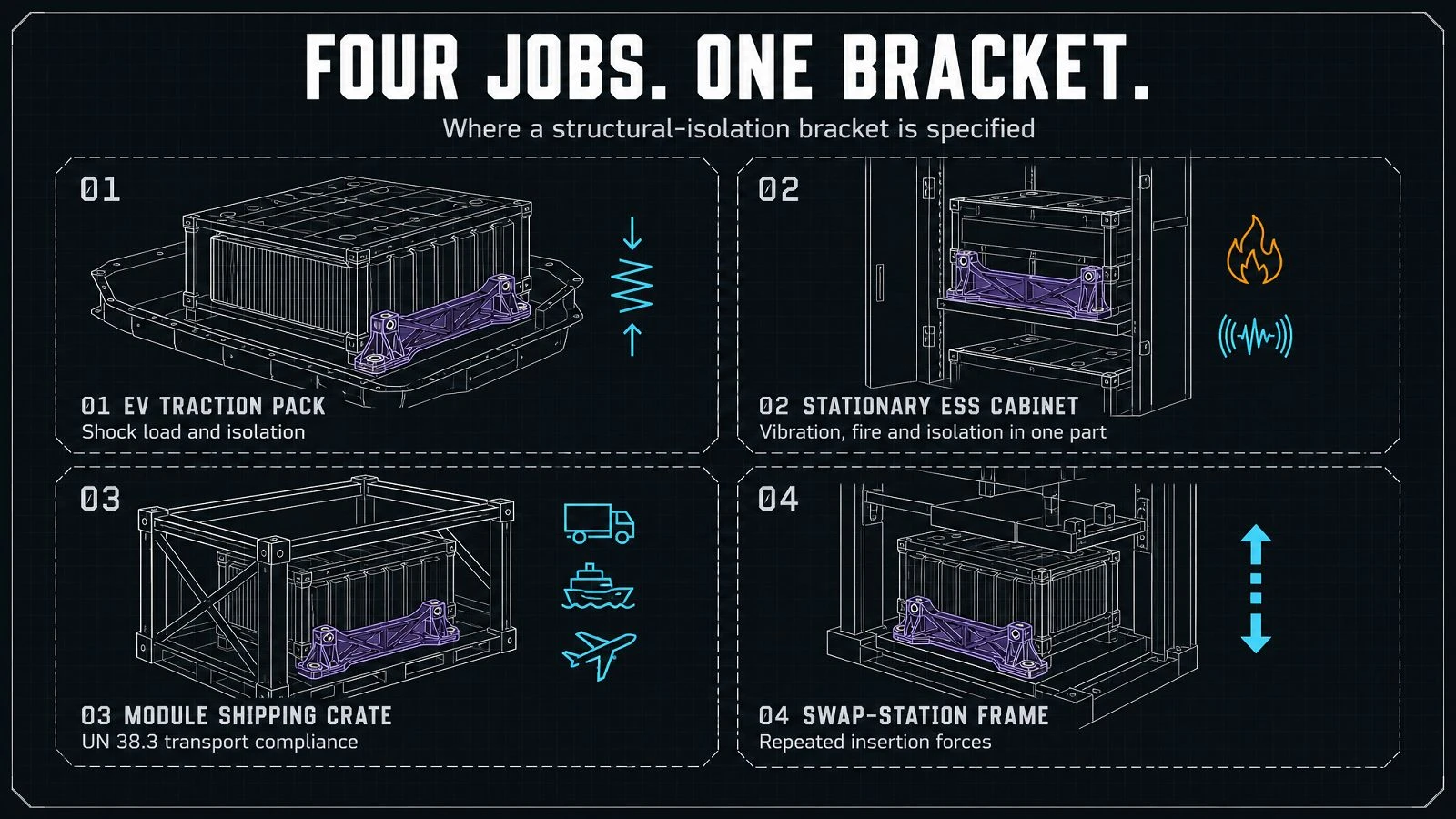
The four use cases for a structural-isolation battery bracket.
EV traction pack
Mount the high-voltage battery module to the vehicle chassis. Needs to carry shock load and remain isolated.
01
Stationary ESS cabinet
Mount battery modules in a stationary cabinet. Vibration, fire, and isolation in one part.
02
Battery module shipping crate
Mount the module for transport by road, sea, or air. UN 38.3 transport test compliance.
03
Battery module swap-station
Mount the module in a swap-station frame. Repeated insertion forces must not degrade the bracket.
04
Structural capacity
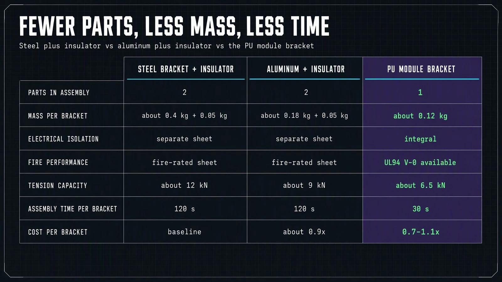
How much load the bracket carries vs the metal alternative.
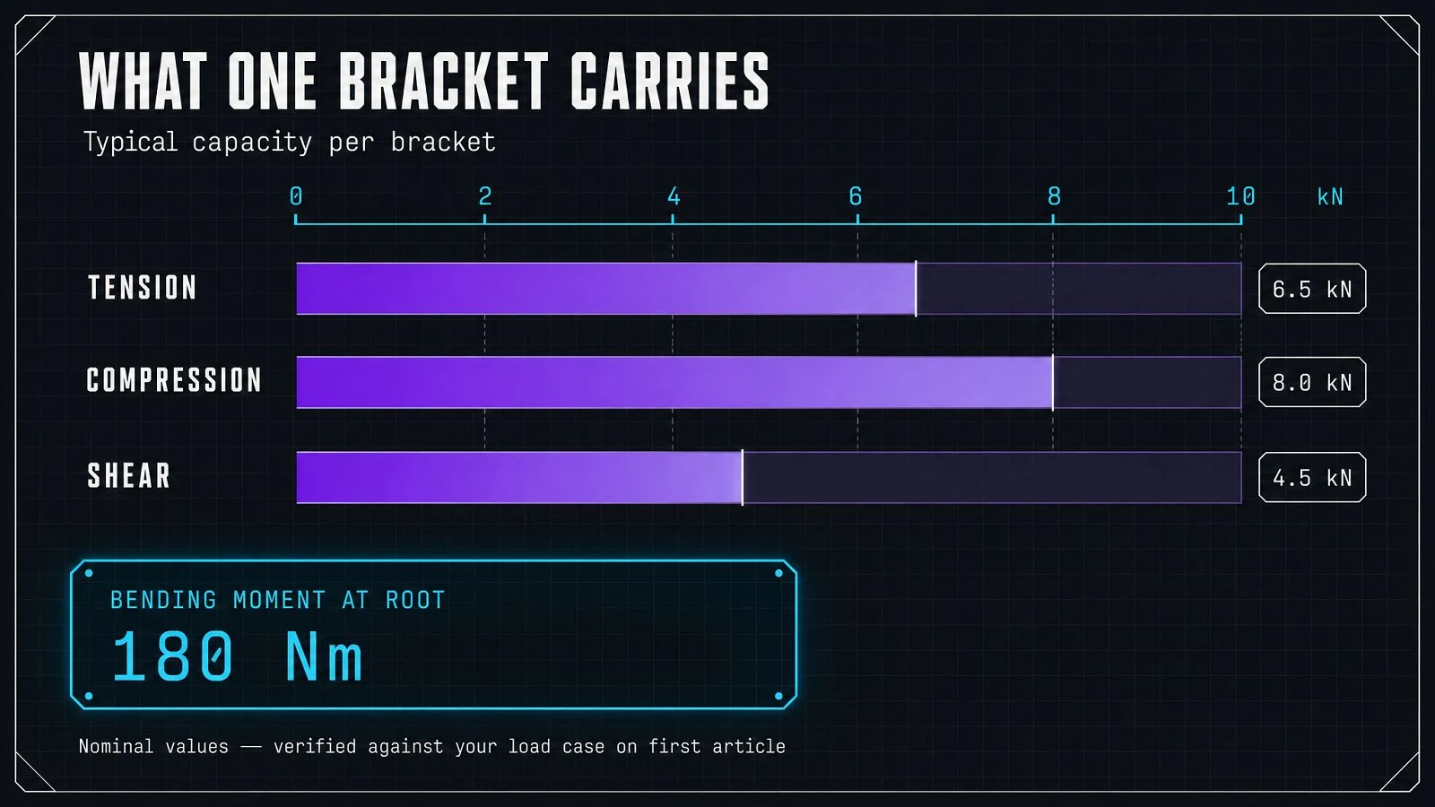
Typical PU module bracket capacity, per part and per the OEM's mounting geometry. Values are nominal; project-specific validation against the OEM's load case is part of first article.
Values above are nominal; verify against your part geometry on first article. PU structural capacity is lower than steel per volume but is sufficient for most battery-module mounting geometries.

Specifications
|
Material |
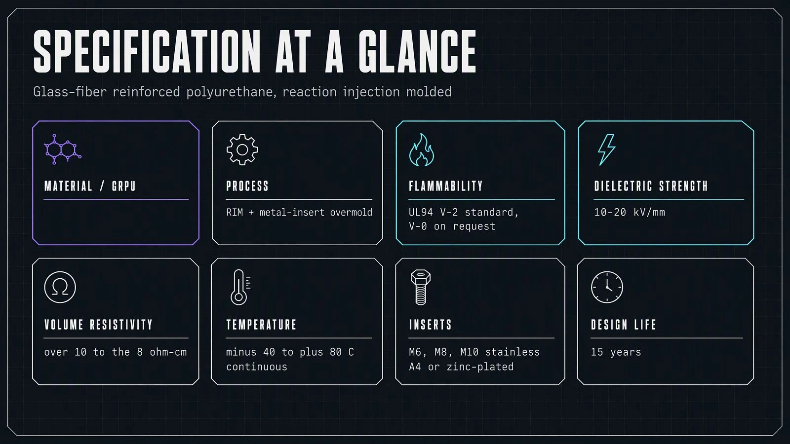
Glass-fiber-reinforced polyurethane (PU / GRPU), UL94 V-2 standard / UL94 V-0 on request |
|
Fiber content |
{{20–40}} % by mass (verify per bracket design) |
|
Process |
Reaction injection molding (RIM) with metal-insert overmold; CNC-machined from solid on request |
|
Standard mount pattern |
M6 / M8 / M10 stainless or steel insert; metric thread standard |
|
Insert material |
Stainless A4 or zinc-plated steel, depending on isolation requirement |
|
Tensile strength |
{{verify published value}} MPa (ASTM D638) |
|
Flexural strength |
{{verify published value}} MPa (ASTM D790) |
|
Compression set |
< {{10}}% per ASTM D395 at design temperature |
|
Electrical |
Non-conductive; volume resistivity > 10⁸ Ω·cm |
|
Dielectric strength |
{{10–20}} kV/mm (ASTM D149) - integral insulation |
|
Operating temperature |
−40 °C to +80 °C continuous; peaks validated per project |
|
Flammability |
UL94 V-2 standard; UL94 V-0 on request |
|
Crash / shock |
Project-specific test against OEM shock load case; standard {{15}}g, 6 ms |
|
Vibration tolerance |
IEC 60068-2-6 (10–500 Hz) at OEM-defined PSD |
|
Chemical compatibility |
Resistant to LiPF₆ and module electrolyte vapors |
|
Color |
Black, grey, or custom RAL |
|
Design life |
15 years |
When not to specify PU module bracket
Cases where metal remains correct.
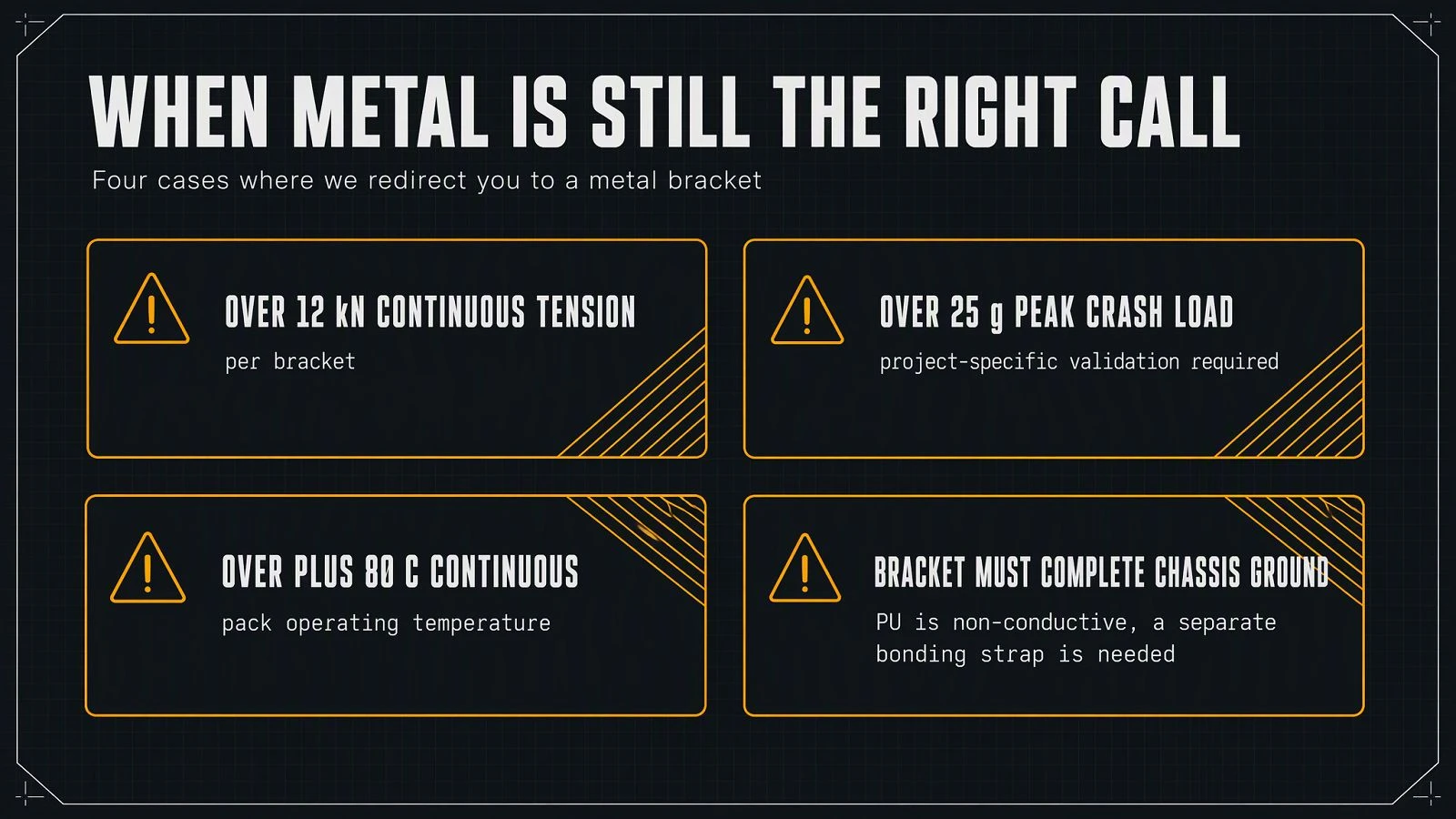
Four cases where we redirect
- Very high continuous structural load. PU structural capacity is sufficient for typical module mounting. Above {{12}} kN continuous tension per bracket, a metal bracket is the right call. Tell us your peak load and we will tell you which is correct.
- Crash load above {{25}} g peak. PU is ductile and absorbs energy, but at very high crash loads the geometry must be validated against the OEM's specific crash case. Project-specific test required.
- Pack operating temperature above +80 °C continuous. Above this temperature, PU compression set and creep accelerate. Different polymer needed.
- Bracket must bond to the chassis electrically (e.g., for EMI grounding). PU is non-conductive. If the OEM's design requires the bracket to complete a chassis ground, a separate bonding strap is needed.

Material comparison
|
Property |
Metal bracket + insulator sheet |
Aluminum bracket + insulator |
Enbuss PU module bracket |
|
Parts in the assembly |
2 (bracket + insulator) |
2 (bracket + insulator) |
1 |
|
Mass per bracket (typical) |
~ {{0.4}} kg (steel) + {{0.05}} kg insulator |
~ {{0.18}} kg (Al) + {{0.05}} kg insulator |
~ {{0.12}} kg |
|
Electrical isolation |
By separate sheet |
By separate sheet |
Integral |
|
Fire performance |
N/A (metal) + fire-rated sheet |
N/A + fire-rated sheet |
UL94 V-0 available |
|
Tension capacity |
~ {{12}} kN |
~ {{9}} kN |
~ {{6.5}} kN (typical) |
|
Assembly time per bracket |
{{120}} s (multi-part) |
{{120}} s |
{{30}} s |
|
Cost per bracket (mid volume) |
Baseline |
~ {{0.9}}× |
~ {{0.7–1.1}}× depending on geometry |
|
Best use case |
High structural load, simple geometry |
Mid load, mid volume |
Most ESS and EV pack modules |
Customization & OEM
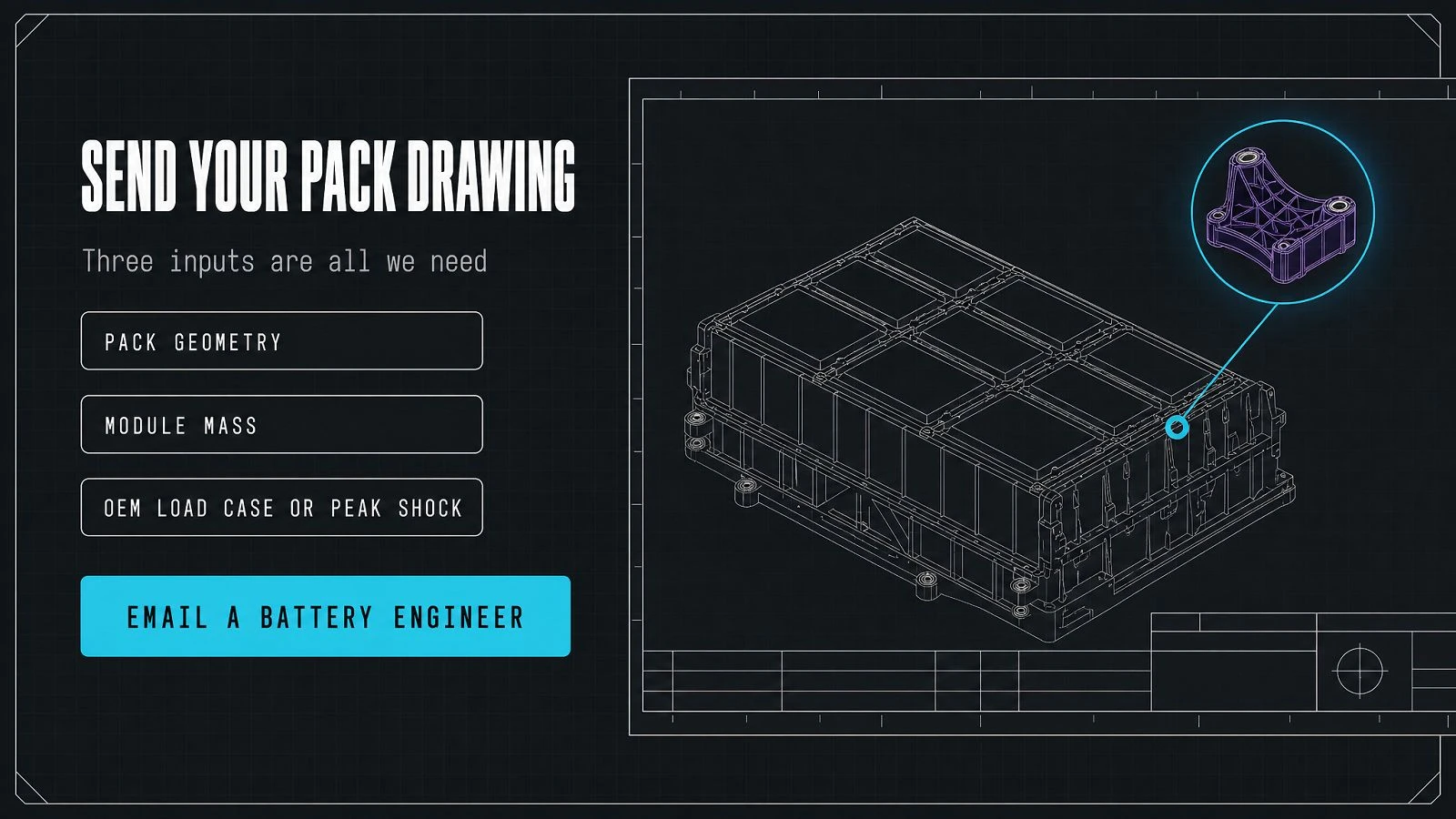
Pack makers typically need a bracket molded to the module and housing geometry with a specific load case. Send your pack drawing; we return a bracket design, a sample, and a fixed quote. First article {{6–8}} weeks; repeat {{4}} weeks. OEM kitting by project available.
Frequently asked questions
What is the typical lead time for a 10,000-bracket order?
From PO to first delivery, typically {{6–8}} weeks for a standard geometry. Custom geometry adds {{2–3}} weeks.
Can the bracket carry vehicle crash load?
Yes, with project-specific test. PU is ductile and absorbs crash energy; specific geometry must be validated against the OEM's crash load case. We supply the test program as part of first article.
Can the bracket be supplied with a bonded metal insert for the housing bolt?
Yes. Stainless A4 or zinc-plated steel insert overmolded in the bracket. Insert is electrically isolated from the rest of the bracket by the surrounding PU.
Is the bracket UL94 V-0 rated?
Yes, on request. Specify on RFQ. The V-0 grade uses a fire-retardant PU formulation; lead time and minimum order quantity are higher than V-2.
How is the bracket inspected in service?
Visual at pack service interval. Replace on visible crack, deformation, or fiber exposure. Service interval typically {{5–7}} years.
Does the bracket react with LiPF₆ electrolyte?
Rated for vapor exposure typical of a sealed module. Direct liquid exposure from a vent event is not tested; vented packs should be evaluated for replacement.
What documentation comes with each lot?
Per lot: dimensional inspection, UL94 certificate (if specified), lot-traceable resin record, structural test coupon report.
What about grounding?
PU is non-conductive. If the OEM's design requires the bracket to complete a chassis ground, a separate bonding strap is supplied by the integrator; we can overmold a bonding clip on request.
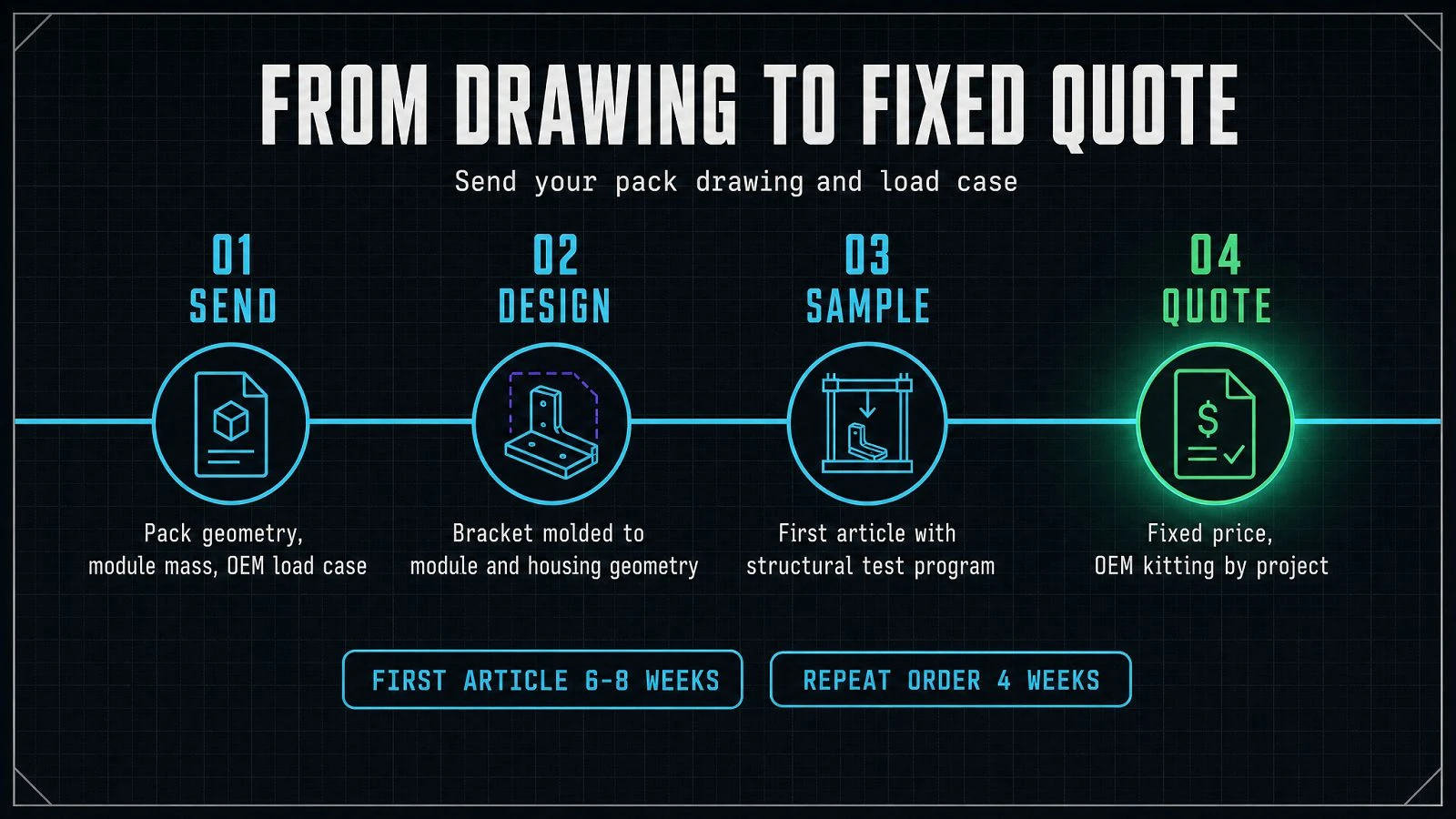
Send your pack drawing and load case
Send the pack geometry, the module mass, and the OEM's load case (or peak shock). We return a bracket design, a sample, and a fixed quote.