

Polyurethane battery compression strip that holds the cell stack under controlled pressure across 5,000 charge cycles
A foam or solid PU compression element placed between the cell stack and the module end plate to apply consistent preload. Replaces metal springs with a controlled force-deflection profile that does not do to metal: creep over the pack lifetime.
Request evaluation samples See force-deflection data
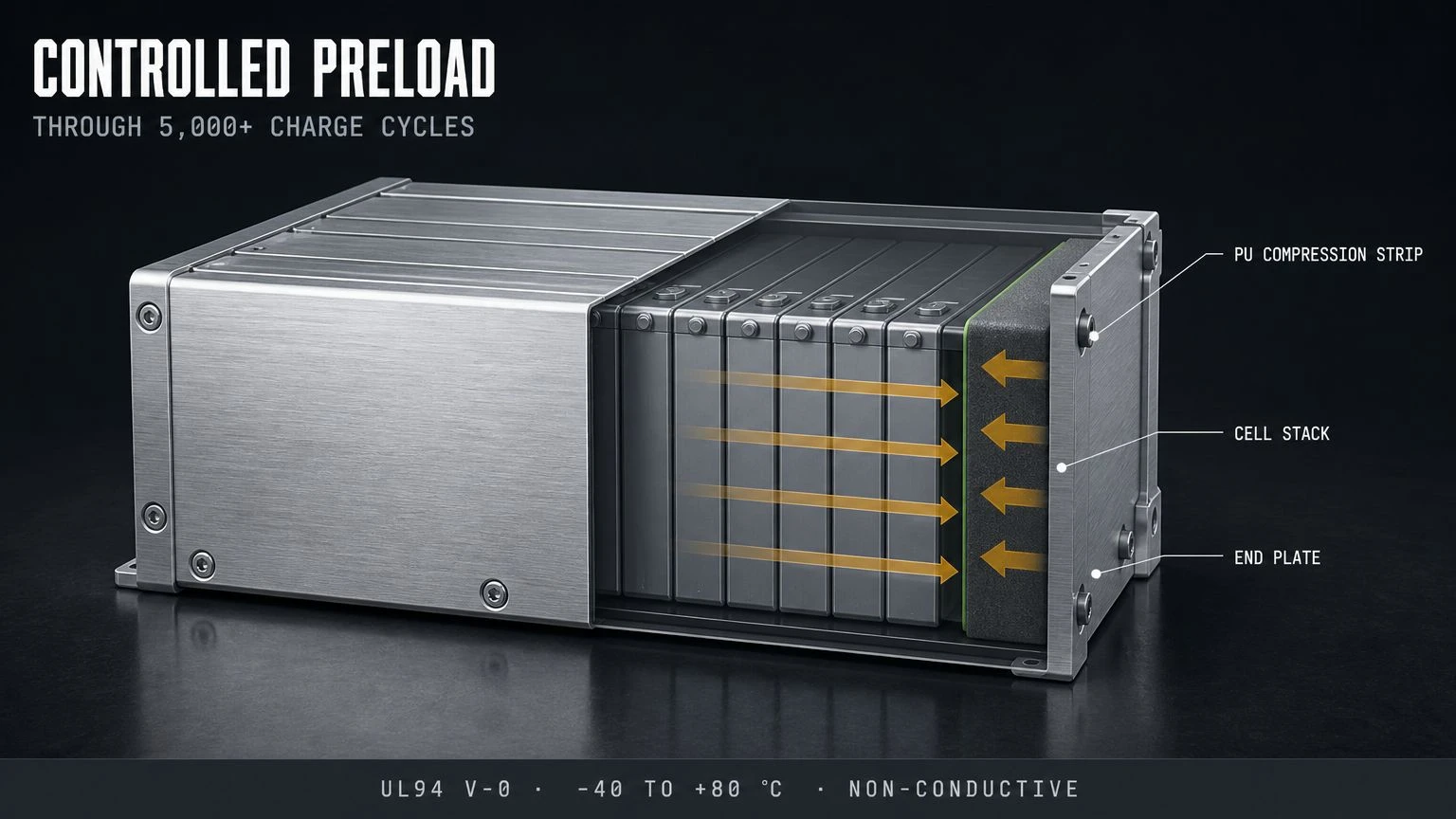
Flame rating (on request)
UL94 V-0
Operating range
−40 to +80 °C
Charge cycles validated
5,000+
Compression set after 1000 h
< {{10}}% creep
What the buyer is trying to solve
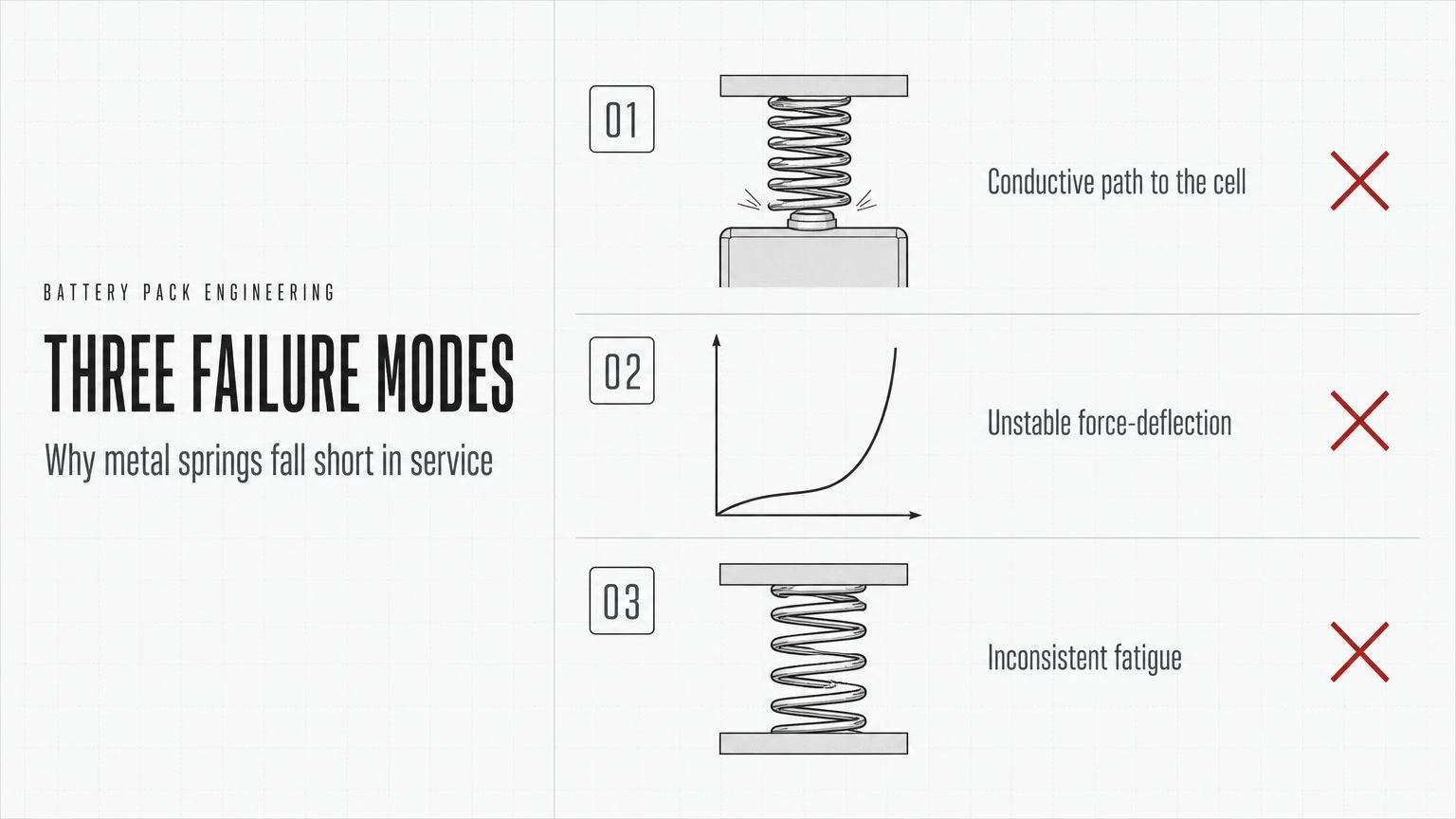
Why battery mechanical engineers arrive at this page.
The buyers who arrive here are battery pack mechanical engineers at ESS integrators or EV pack makers. They are designing the compression system that holds prismatic or pouch cells together across the pack lifetime. The conventional choice is a metal coil spring, which is fine in compression but has three problems in service: it is conductive (so it can create an unintended short-circuit path if a cell swells into it), it has an unstable force-deflection curve at high compression, and its fatigue behavior under 5,000 charge cycles is inconsistent. The PU compression strip solves all three.
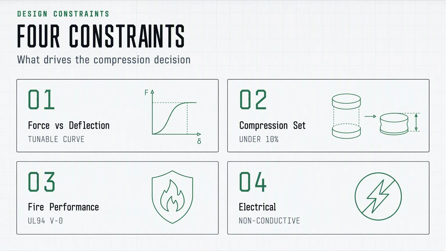
The four engineering constraints that drive the decision
- Compression force vs deflection curve. The cell stack swells during charge; the compression strip must maintain force across the expected swell without over-compressing when new.
- Compression set over time. The strip must not lose preload after 1,000 hours of operation. PU compression set below {{10}} percent at the design temperature is the typical target.
- Fire performance. In a thermal event, the strip must not propagate flame. UL94 V-0 grades are available.
- Non-conductivity. The strip must be electrically isolating; metal springs can short if a swollen cell makes contact.
Force-deflection profile
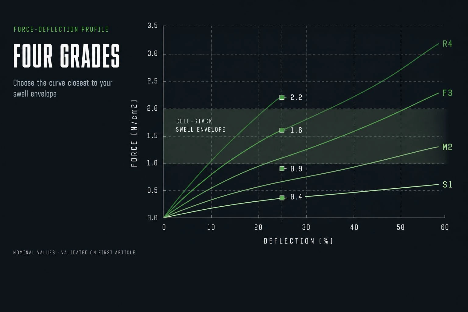
Typical strip grades; values are nominal and validate per part drawing.
Different PU grades give different force-deflection profiles. Choose the grade whose curve sits closest to your cell-stack swell envelope. Below is a representative family - actual curves are validated against your sample.
Force at 25 % deflection (representative)

Force-deflection data is validated against your sample on first article. Values above are nominal for illustration; not for design use.
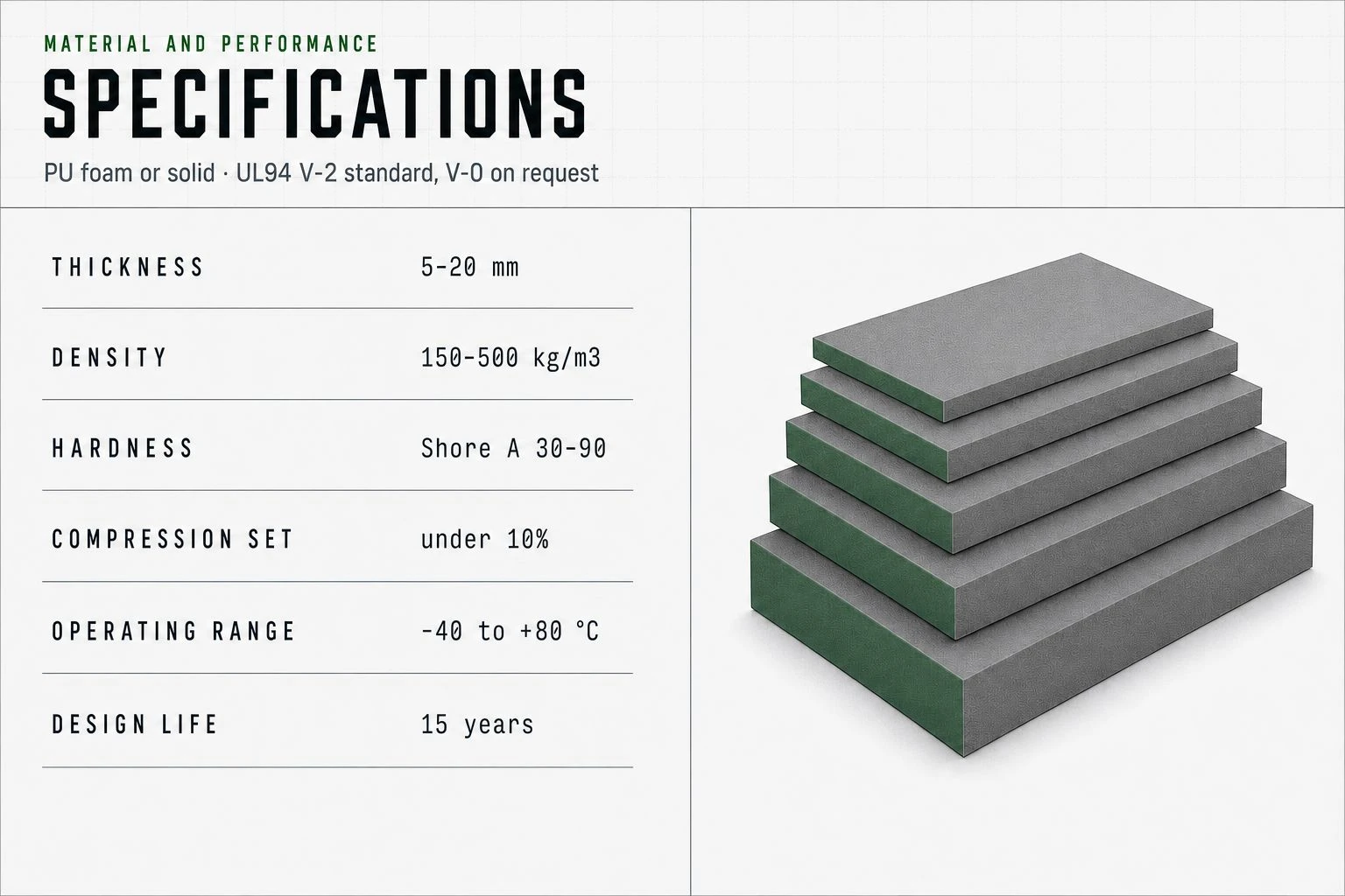
Specifications
|
Material |
Polyurethane foam or solid PU; UL94 V-2 standard, UL94 V-0 on request |
|
Cell format compatibility |
Cylindrical (18650, 21700, 4680), prismatic (VDA / automotive), pouch (with rigidizer) |
|
Standard thicknesses |
{{5, 8, 10, 15, 20}} mm; custom to {{50}} mm |
|
Standard widths |
Per cell-stack width; custom cut to length |
|
Density (foam grades) |
{{150–500}} kg/m³ (varies by grade) |
|
Hardness (solid grades) |
Shore A {{30–90}} (varies by grade) |
|
Compression set |
< {{10}}% at {{70 °C × 22 h per ASTM D395}} |
|
Operating temperature |
−40 °C to +80 °C continuous; higher peaks validated per project |
|
Flammability |
UL94 V-2 standard; UL94 V-0 on request |
|
Electrical |
Non-conductive; volume resistivity > 10⁸ Ω·cm |
|
Chemical compatibility |
Resistant to LiPF₆ electrolyte vapors; validated per project |
|
Charge-cycle endurance |
Validated to 5,000 cycles per project test protocol |
|
Color |
Black or grey standard; other colors on request |
|
Design life |
15 years (matches ESS pack lifetime) |
When not to specify PU compression strip
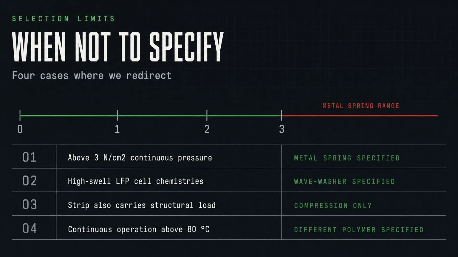
Cases where a different compression element is correct.
Four cases where we redirect
- Compression force above {{3}} N/cm² continuous. Above this range, the strip deforms permanently; the metal spring or wave-washer is the right element. Tell us your peak preload and we will tell you whether PU or metal is correct.
- Cell format with extreme cycling depth and high swell. Some LFP or high-swell chemistries push the strip into compression ranges where PU ages faster than the pack. Wave-washers may be specified for these cells.
- Strip carries structural load beyond compression. The strip is for compression only; if the battery module bracket also acts as a structural support, see our PU module bracket page.
- Continuous operation above 80 °C. PU compression set degrades above this temperature. Above 80 °C continuous, we specify a different polymer. Tell us your pack's worst-case ambient.
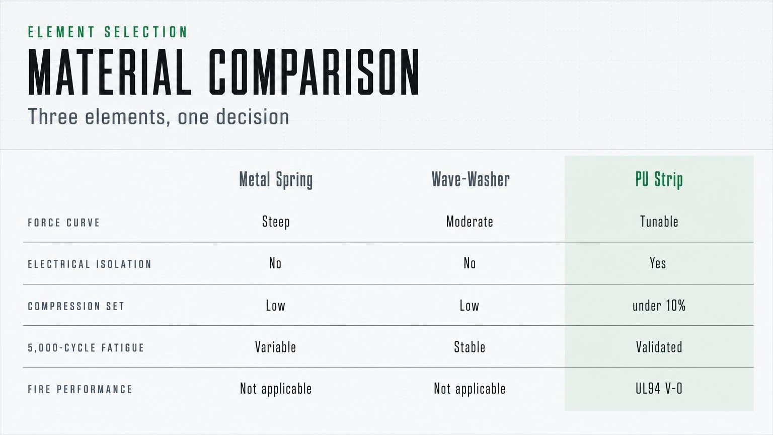
Material comparison
|
Property |
Metal coil spring |
Wave-washer |
Enbuss PU compression strip |
|
Force-deflection curve |
Steep - small deflection, big force change |
Moderate |
Tunable - close to linear in working range |
|
Electrical isolation |
Conductive |
Conductive |
Non-conductive |
|
Compression set at design T |
Low |
Low |
Acceptable (< {{10}}%) |
|
Fatigue at 5,000 cycles |
Variable - risk of fatigue failure |
Acceptable |
Validated |
|
Fire performance |
N/A (metal) |
N/A |
UL94 V-0 available |
|
Cost per cell stack |
Low (commodity) |
Mid |
Mid - replaced less often |
|
Best use case |
Very high continuous compression |
Mid compression, harsh env |
Most cell-stack compression profiles |
Customization & OEM
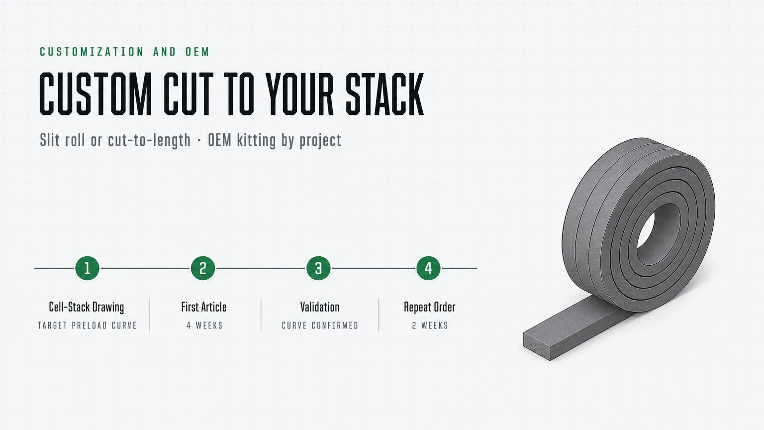
ESS integrators and EV pack makers typically need a custom-cut strip to the cell-stack dimensions, with a specific force-deflection curve and a published UL94 rating. We supply the strip in slit roll or cut-to-length format; OEM kitting by project available. Send your cell-stack drawing and the target preload curve. First article {{4}} weeks; repeat {{2}} weeks.
Frequently asked questions
What is the typical lead time for a 10,000-strip order?
From PO to first delivery, typically {{4–6}} weeks for a standard grade in black. Custom grade adds {{2}} weeks. We hold forecast slots for major ESS integrators; ask your account engineer.
Can the strip be supplied with adhesive backing?
Yes, pressure-sensitive adhesive on one face for assembly-line placement. Specify on RFQ.
How is compression set tested?
Per ASTM D395, method B at the design temperature. Standard test is 22 hours at 70 °C. Project-specific tests can extend duration and temperature to validate cell-stack-level conditions.
Does the strip react with LiPF₆ electrolyte?
The standard PU formulation is rated for the vapor exposure typical of a sealed cell module. Direct liquid exposure is not tested - if a cell vents, the strip may be compromised and the pack should be evaluated for replacement.
Can the strip be cut on site?
Yes - sharp knife or die-cut. Custom-cut strips ship ready to install.
Is the strip recyclable at end of pack life?
PU can be glycolyzed to recover polyol. We offer a take-back program in pilot regions; ask your account engineer.
How is the strip inspected in service?
Visual at pack service interval. Any visible deformation, cracking, or permanent set above the design value indicates replacement. Pack service schedule typically {{5–7}} years.
What documentation comes with each lot?
Per lot: dimensional inspection, compression set test, UL94 certificate (if specified), density or hardness, lot-traceable resin record.
Send your cell-stack drawing and target preload curve
Send the cell format, the cell-stack dimensions, and the target compression force at design deflection. We return a strip sample, the published force-deflection curve, and a fixed quote.