

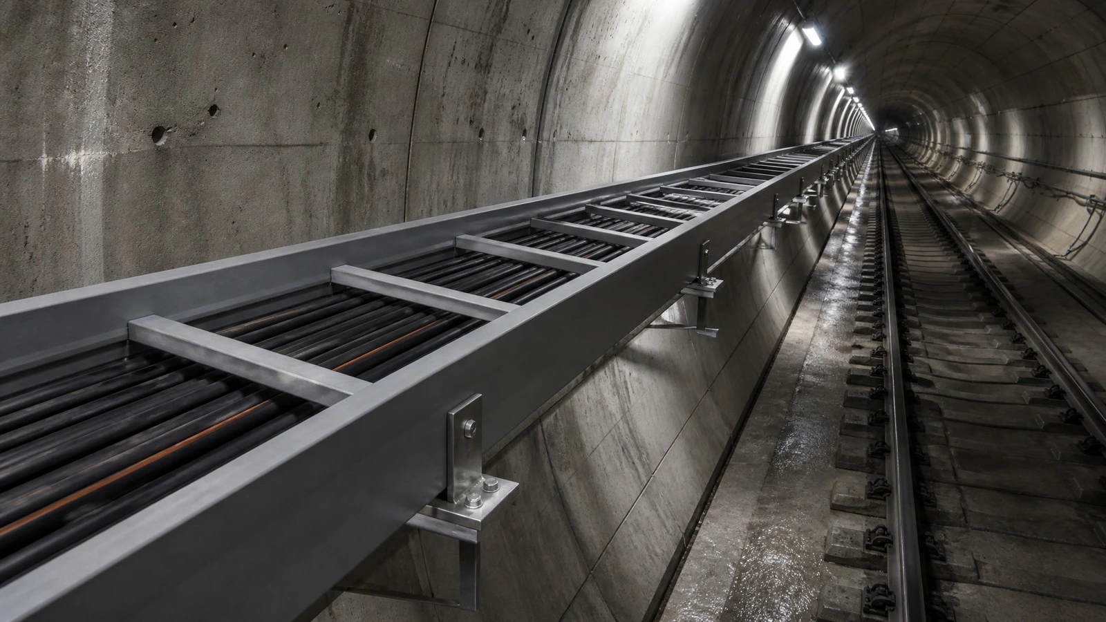
FIBERGLASS CABLE SUPPORT · RAIL TRANSIT
FRP cable tray that carries the load, kills the stray current, and never worries about corrosion
Composite ladder, perforated, and solid-bottom cable tray for tunnel, viaduct, and substation cable runs in 25 kV AC electrified rail and DC-traction metro systems. Tested to IEC 61537. Designed to be specified by electrical engineers who have been told "no metal" by the EMC team.
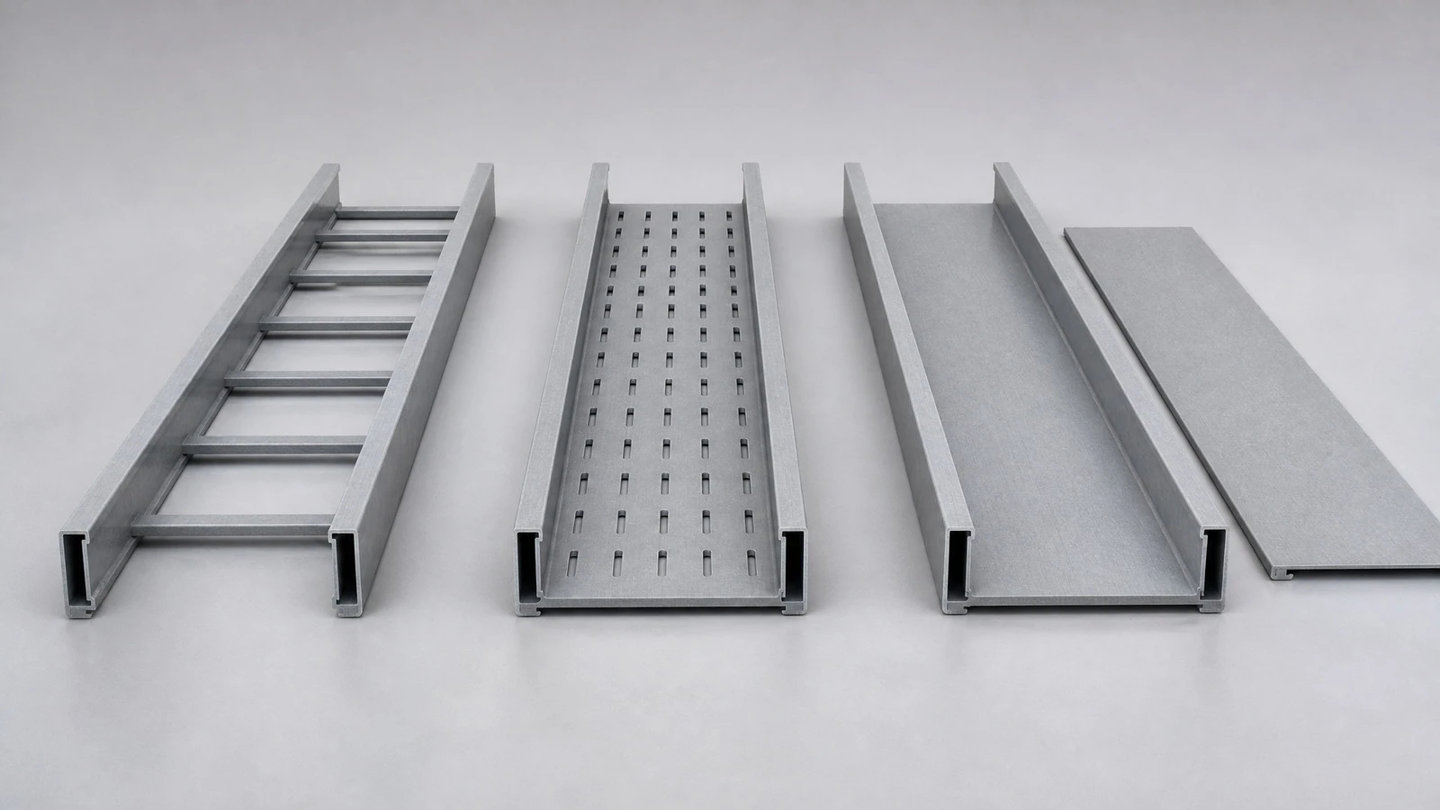
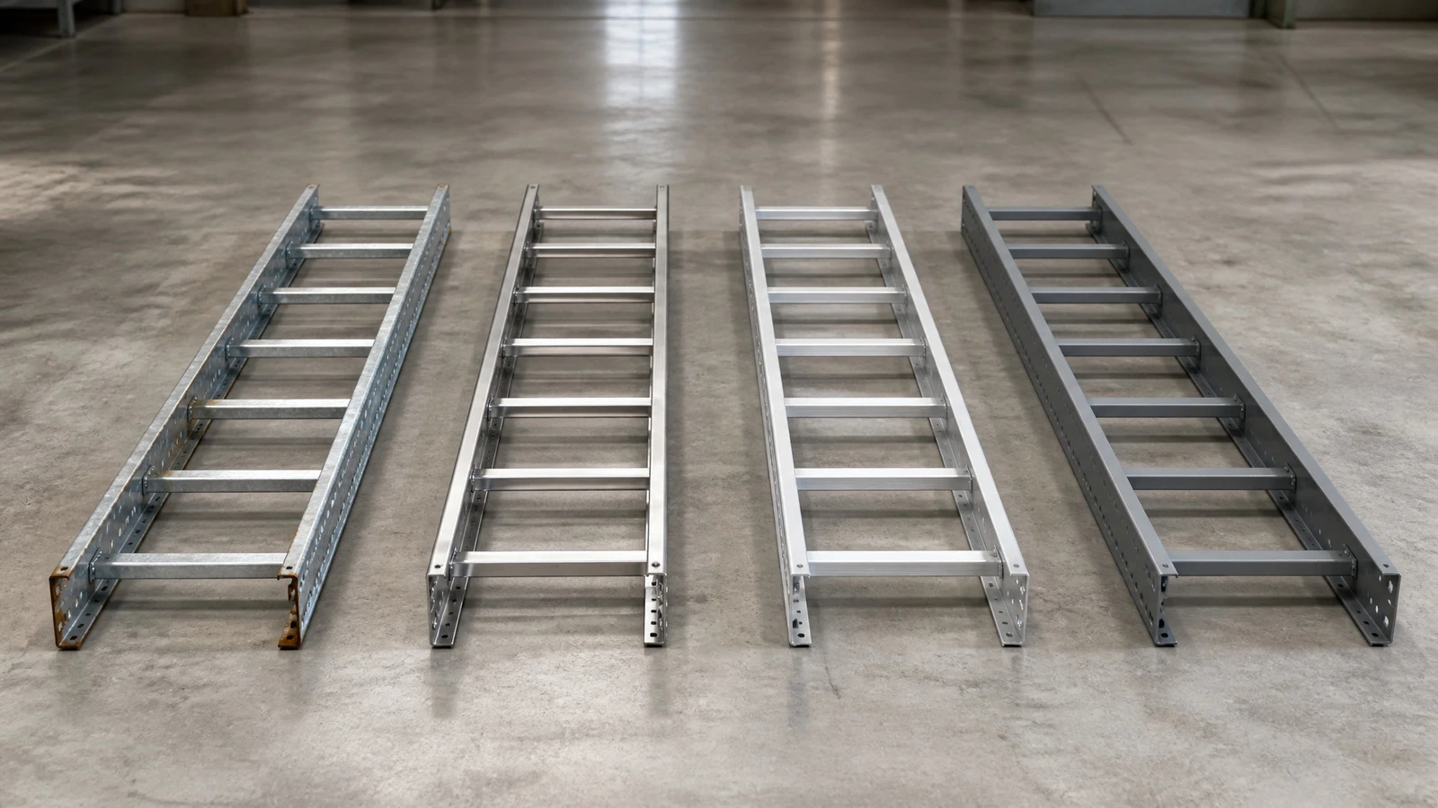
- Types: Ladder, perforated, solid-bottom
- Widths: 100–900 mm
- Loads: IEC 61537 A–E
- Span: Up to 6 m
SIZE & LOAD SELECTION - START HERE
Ladder type is the default for long tunnel runs with significant cable mass; perforated for instrumentation and signal cables where some airflow is wanted; solid-bottom where you want to contain a small leak rather than let it drip onto the rail. Working load per IEC 61537.
|
Type |
Width (mm) |
Height (mm) |
Working load (N/m) |
Span (m) |
Default resin |
Use case |
|
Ladder L1 |
150 |
60 |
120 |
1.5 |
Vinyl-ester |
Light signal cables under platform |
|
Ladder L2 |
300 |
100 |
240 |
2 |
Vinyl-ester |
Main tunnel corridor, signal + power |
|
Ladder L3 |
450 |
100 |
300 |
2.5 |
Vinyl-ester |
Heavy 25 kV OCS feeds |
|
Ladder L4 |
600 |
150 |
380 |
3 |
Vinyl-ester |
Substation outgoing feeders |
|
Ladder L5 |
900 |
150 |
450 |
3 |
Vinyl-ester |
Combined-services backbone |
|
Perforated P2 |
300 |
60 |
120 |
2 |
Vinyl-ester |
Signal instrumentation |
|
Perforated P3 |
450 |
100 |
240 |
2.5 |
Vinyl-ester |
Trackside signaling |
|
Solid-bottom S2 |
300 |
100 |
180 |
2 |
Vinyl-ester |
Cable containment over passenger areas |
|
Solid-bottom S4 |
600 |
150 |
280 |
2.5 |
Vinyl-ester |
Viaduct run under expansion joints |
|
Custom |
to 1200 |
to 200 |
per calc. |
to 6.0 |
Phenolic on request |
Substation main runs, HL3 lines |
WHY THIS PAGE EXISTS
What the buyer is actually trying to solve
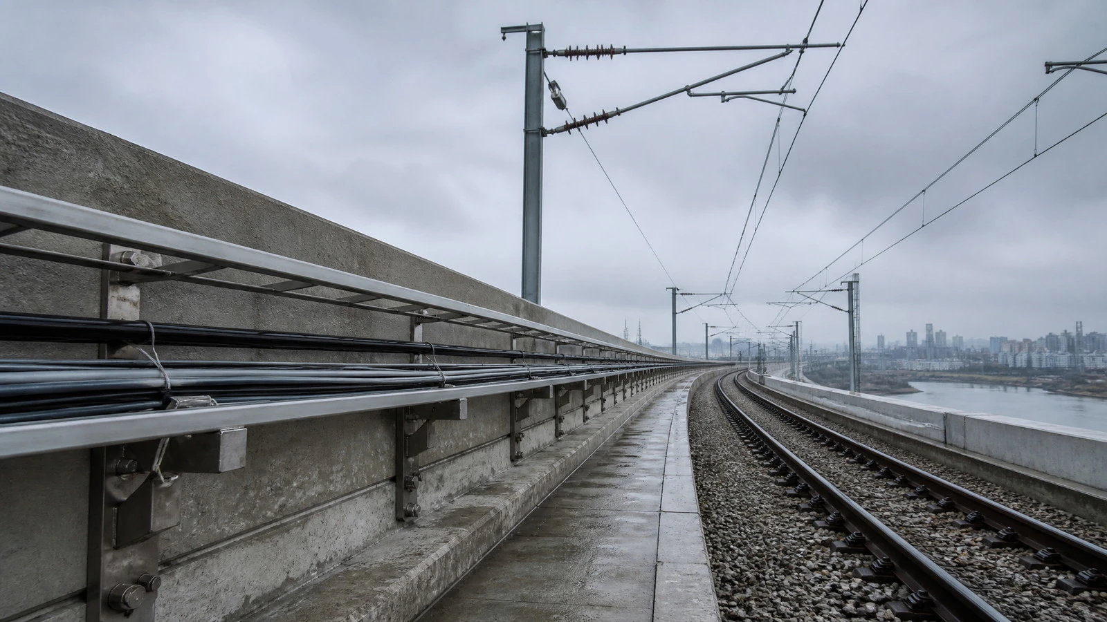
Electrical engineers on rail projects arrive here after a working session that went something like this: the EMC or stray-current consultant has told them that the steel cable tray they originally specified is a problem, because steel in a DC-traction tunnel becomes a parallel path for traction return current, accelerating corrosion of rebar and concrete spalling. Aluminum is conductive - also out. Stainless is allowed but expensive, heavy, and still has the parallel-path problem. The remaining option is FRP, and that is what this page exists to support.
The four engineering questions behind every RFQ
Stray-current isolation
Volume resistivity above 10⁸ Ω·cm makes the tray invisible to the traction-return circuit.
Span and load capacity
How much cable can the tray carry over how long a distance? Defaults in the table above; calc for the rest.
Fire performance
EN 45545-2 HL2 standard; HL3 from a phenolic resin. Metro specs usually dictate.
Fittings, bends, risers
Factory-fabricated bends save on-site time. We ship flat-pack with bend drawings, or pre-routed.
THE PRODUCT IN DETAIL
The cable tray, as actually built
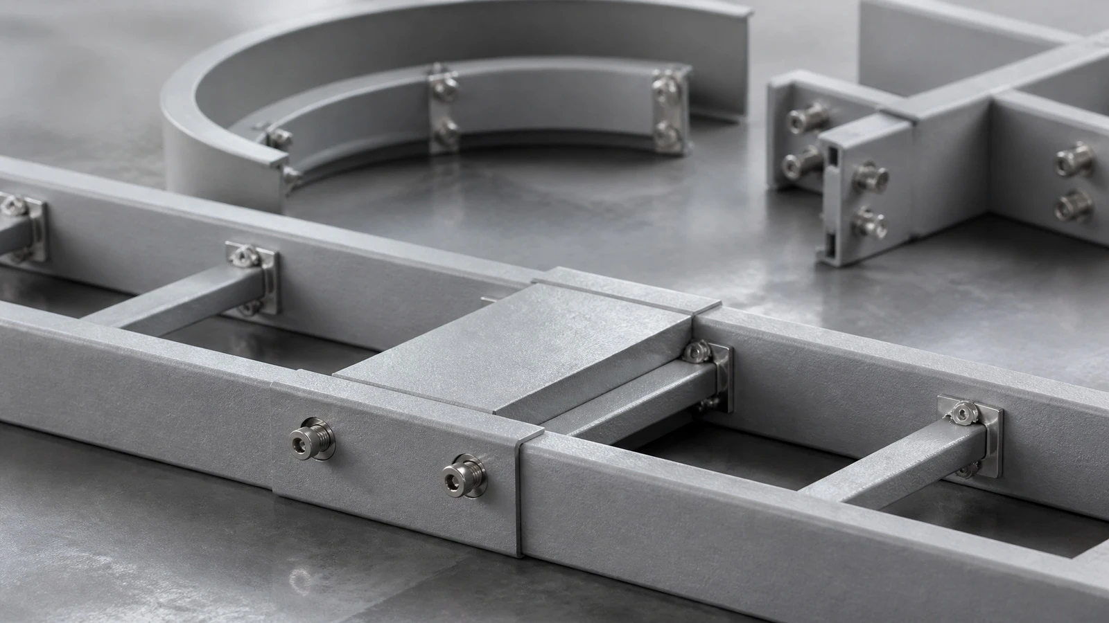
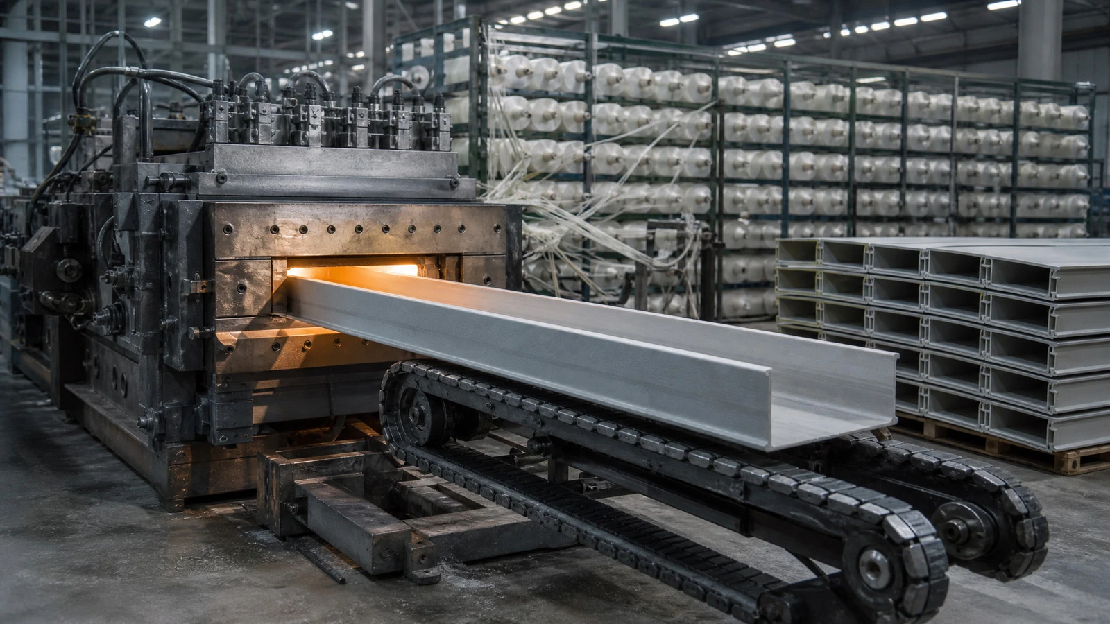
Enbuss rail-transit cable tray is a pultruded ladder or trough profile, cut and bonded with factory-fabricated fittings. Resin, glass schedule, and the surface veil are designed for one job: support cable in a 25 kV or 750 V DC tunnel, 25 years, with no surprise.
Standard sections and what they are made of
Ladder rails are pultruded vinyl-ester with electrical-grade glass roving schedule. Rungs are pultruded and mechanically locked into the rail (not bonded only). Couplers are pultruded sleeves with stainless through-bolts - no metal exposed to cable damage. Covers are an optional separately-quoted accessory.
Fittings factory or site-built
For long runs, factory fittings cut on-site time dramatically. We supply elbows, tees, risers, reducers, and cross-overs machined from the same pultrusion, dimensionally matched to the straight sections. For unusual geometry, we issue site-cut kits with adhesive-bonding protocol and an angle template.
WHEN NOT TO USE
Four cases where a different cable support is the right answer
- You need to walk on the tray. FRP ladder is not a walkway. If maintainers step on it, specify a steel walkway alongside (or replace with a steel wire mesh basket, accepting the stray-current compromise and noting it on drawings).
- The tray is in direct sunlight above ground. UV will chalk unprotected pultrusions. Specify a UV-stable gelcoat or a different material.
- Cable weight exceeds {{450}} N/m on a {{3 m}} span. Step up to a heavier steel or pre-cast concrete support. FRP cable tray at this scale needs to be engineered case-by-case.
- The tray is in a hazardous area requiring ATEX certification. Not our standard product - we can quote ATEX, expect {{8–10}} weeks lead time.
MATERIAL DECISION
How each material handles the four rail-tunnel constraints
|
Constraint |
Hot-dip galvanized steel |
Stainless 316 |
Aluminum |
Enbuss FRP |
|
Stray-current path to rebar |
Yes - major |
Yes - major |
Yes - via aluminum oxide film breakdown |
No - insulator |
|
Cost over 20 years (coating + replace) |
High - replace at year 12–15 |
Lower than galv., but high capex |
Mid; lower than galv. |
Lowest - 25-yr design life, no recoat |
|
EN 45545-2 HL3 achievable |
With intumescent coating |
Yes |
No - melts |
Yes - phenolic resin option |
|
Cutting and drilling on site |
Easy |
Easy |
Easy |
Diamond blade; seal cut edges |
|
Mass per metre (450 mm ladder) |
~ 12 kg/m |
~ 12 kg/m |
~ 5 kg/m |
~ {{3.5}} kg/m |
|
Magnetic interference |
Yes - affects signaling |
Reduced, not zero |
No |
No |
The data come from the IEC 61537 published working loads for the same N/m class. Project-specific calculations live in your electrical design package; bring them to your quote.
SPECS
Engineering specifications
|
Resin |
Vinyl-ester (FR); phenolic (HL3); isophthalic (economy) |
|
Glass reinforcement |
Electrical-grade E-glass roving + mat; surface veil |
|
Standard length per piece |
6 m (container-friendly); 3 m on request |
|
Fire performance |
EN 45545-2 HL2 (FR vinyl-ester); HL3 (phenolic); ASTM E84 Class A on request |
|
Volume resistivity |
> 10⁸ Ω·cm (non-conductive) |
|
Dielectric strength |
{{5–10}} kV/mm (ASTM D149) |
|
Working load range |
120–450 N/m standard (IEC 61537 classes A–E; higher on request) |
|
Operating temperature |
−40 °C to +80 °C continuous |
|
UV package |
UV-stable gelcoat or topcoat for above-ground runs; no finish for tunnel |
|
Coupler material |
Pultruded FRP sleeve + stainless A4 through-bolts |
|
Standards |
Designed to IEC 61537; tested to ASTM D638 / D790; fire to EN 45545-2; UV to ASTM G154 |
|
Design life |
25 years (FR), 30 years (phenolic) |
|
Color |
Grey RAL {{7035}} standard; safety yellow on request |
CUSTOM / OEM
Custom geometry, OEM kitting

OEM customers usually need a complete kit: tray + supports + brackets + covers + bonding instructions, packaged per run and shipped with installation drawing number on each bundle. We do that as a service: provide the run schedule, we build the kit. First article {{6}} weeks; repeat {{3}} weeks. PE-stamped calculation pack available on request.
FAQ
Frequently asked questions
What is the typical lead time for a 5 km order?
From PO to first delivery, typically {{8–10}} weeks for a mix of L2 and L3 ladder in vinyl-ester. Phenolic resin adds {{4–6}} weeks. We hold forecast slots for major programs - talk to your account engineer early.
Can the tray be supplied with pre-fabricated bends?
Yes. Standard bends (90° flat, 90° riser, tee, reducer, cross) are factory-fabricated and ship in matching lengths. Non-standard geometry ships as site-cut kits with adhesive-bonding protocol.
How is the tray supported to the wall / ceiling?
Through stainless or composite cantilever brackets, distance set per the engineering package. We supply matching brackets sized to the tray height; standard spacing table is in the catalog.
Does FRP tray pass through fire-rated walls?
Yes, with a fire-rated wall penetration kit. We provide intumescent foam-and-mastic kits tested to {{2}} hour FRL; specify on RFQ.
What happens if a section is damaged on site?
Damaged pultruded sections can be cut out and replaced using our splice-coupler kit. The repair is structural and matches the original load class. A one-page repair procedure ships with every order.
How does the tray behave with fiber optic cable?
FRP is chemically inert to cable jacket materials and creates no mechanical abrasion at normal bend radius. For very long fiber runs we recommend solid-bottom type to control bend radius.
Is the tray recyclable at end of life?
Vinyl-ester pultrusions can be shredded and used as filler in non-structural concrete. We offer a take-back program for pilot regions; ask your account engineer.
How is the coupon certified for fire?
Lot-traceable test report per resin batch against EN 45545-2. Project-required HL2 / HL3 confirmed in writing with shipment.
Send a cable run schedule
Send the run length, cable OD and mass per metre, and the number of bends. We return a bill of materials, a lead time, and a fixed quote.